Search
Search Results
SearchPower-On Setting ,
find 17 items
- Sort by
- Most recent
- Popularity

Product
Application
Seminar
Watch time - 3:18
AppWizard is a graphic human-machine interface design tool that supports the emWin graphics library. This tool allows GUI design and development to be completed with minimal coding using a drag-and-drop interface and settings.
This demo showcases the use of the AppWizard tool with the M467 development platform to design an electric bicycle dashboard interface. Therefore, the video will be divided into two parts: the M467 development platform introduction and the key features of the AppWizard.
#en #Product #Application #General #Seminar
#2023 Roadshow #Nuvoton #Nuvoton #E-bike #Dashboard #emWin AppWizard #NuMicro #MCU #M467
-
For more information, please visit Nuvoton Technology Website: https://bit.ly/3hVdcmC
buy now: https://direct.nuvoton.com/
contact us: SalesSupport@nuvoton.com

Application
Learning
Watch time - 2:49
This video will introduce the NuMicro M031BT/M032BT series of Nuvoton BLE MCUs in photographic lighting applications. Through excellent control functions, multiple I/O settings and the advantages of wireless transmission, it can help customers reduce the cost of developing photographic lighting and time to market.
#Application #Learning #Intermediate #en
#Bluetooth #SmartDevice #PassThrough #CentralMode #PeripheralMode #M031BT #M032BT #BLE #MCU #Nuvoton #Spotlight #NuMicro #EmbeddedWorld2022
-
For more information, please visit Nuvoton Technology Website: https://bit.ly/3hVdcmC
buy now: https://direct.nuvoton.com/tw/
contact us: SalesSupport@nuvoton.com

Application
Learning
Watch time - 2:32
This video will introduce Nuvoton BLE MCU NuMicro M031BT/M032BT series applied to electronic massage equipment, with the advantages of excellent control functions, multiple I/O settings and wireless transmission to reduce the cost of developing products and to assist clients time to Market.
#Application #Learning #Intermediate #en
#Bluetooth #ElectronicMassageEquipment #DigitalLife #pass-through #CentralMode #PeripheralMode #EmbeddedWorld2022 #M032BT
-
For more information, please visit Nuvoton Technology Website: https://bit.ly/3hVdcmC
buy now: https://direct.nuvoton.com/tw/
contact us: SalesSupport@nuvoton.com

Product
Tool
Learning
Watch time - 8:24
The video introduces Nuvoton's MPU N9H30's development set-up for Linux and Non-OS, taking NuMaker-emWin-RDK-N9H30 for example. Starting from the EVB introduction to BSP and related software downloads.
-
User manuals and related resource can be downloaded
https://www.nuvoton.com/products/gui-solution/gui-reference-design/numaker-emwin-rdk-n9h30/
First, we introduce how to program Linux OS to the N9H30 evaluation board
Find the N9H30 evaluation board resource that we used on Nuvoton’s Github and download the VMware Image
https://github.com/OpenNuvoton/MPU-Family
VMware application can be downloaded from the VMware website
https://www.vmware.com/tw/products/workstation-player/workstation-player-evaluation.html
First, open the VMware
Find the ubuntu_NUC970_980_Linux folder we downloaded
Choose Ubuntu 64-bit_nuvoton.vmx
Choose Play virtual machine
The password is “user”
It will take a while to open this application for the first time
Open the terminal when the system is ready
Enter NUC970_Buildroot-master folder
After entering the folder, we need to update the Buildroot tool
Enter the command as shown below
“git reset –hard”
“git pull”
After updating, enter the dl folder
Remove the original Linux kernel and u-boot
Enter the command as shown below
“sudo rm -rf linux-master.tar.gz uboot-master.tar.gz”
After entering, enter the password “user”
Leave the dl folder and enter the Buildroot folder
Enter the “make clean” command
You don’t need to do these steps unless updating Buildroot tools
Now, we set up the evaluation board configuration
Enter configs folder to search evaluation board name
Back to buildroot after searching
Enter “make nuvoton_n9h30_emwin_defconfig” to generate configuration file
After finishing these step, enter “make” to compile
It will take about three hours to compile
After compiling, copy the two files below to windows
“/NUC970_Buildroot-master/output/images/uImage”
“/NUC970_Buildroot-master/output/build/uboot-master/u-boot.bin”
Create text file ”env-nor.txt”
The content is shown below:
baudrate=115200
bootdelay=1
stderr=serial
stdin=serial
stdout=serial
setspi=sf probe 0 50000000
loadkernel=sf read 0x7fc0 0x200000 0x600000
bootcmd=run setspi;run loadkernel;bootm 0x7fc0
bootargs=noinitrd root=/dev/mtdblock2 rw rootfstype=jffs2 console=ttyS0 rdinit=/sbin/init mem=32M mtdparts=m25p80:0x200000@0x0(u-boot),0x600000@0x200000(kernel),-(user) ignore_loglevel
Then, we need to install NuWriter and related file
The NuWriter is a programming tool provided by Nuvoton. The NuWriter application and firmware code are open-sourced, and users can add new features or develop new user interfaces per user’s application
NuWriter: https://github.com/OpenNuvoton/MPU-Family
Open “NUC970_NuWriter-master”
Enter Driver folder and install “WinUSB4NuVCOM.exe”
Enter /Nuwriter/Release and execute NuWriter
Choose IC number based on the evaluation board
We need to program Image to SPI Flash, so we choose SPI
Here we need to turn the all Power-On Setting to ON
Push Reset button
Return to NuWriter to check the green light and the connection
If it is not connecting, click Re-Connect to reconnect
After confirm the connection, start to program Image
Program the three files to particular address
u-boot.bin program to 0xe00000
env.nor.txt program to 0x80000
uImage program to 0x200000
After programming, turn the Power-On Setting to off
Push the Reset button
Evaluation board can start to boot from SPI-NOR
After booting, we need to find the rcS demo application under/etc/init.d
Enter “chmod 777 rcS” to modify the application
Now, you can see the application on the evaluation board panel
Here, we finish compiling and programming
The next topic is how to compile and program Non-OS code
First, download MDK-Arm from the link below
https://www.keil.com/download/product/
Download the Non-OS BSP provided by Nuvoton
https://github.com/OpenNuvoton/MPU-Family
The BSP includes Keil environment set up user manual
Use Keil need to purchase the related license
After downloading, Open Keil uVision
Click the File on the upper left and choose Open
Go to the BSP that we downloaded choose BSP, SampleCode, emWin_SimpleDemo, KEIL and emWin_SimpleDemo.uvproj
Click Option for Target
Click Device and choose NuMicro ARM9 Database and N9H_series
After setting up, click Rebuild, and it will generate a sample code application which is a binary file
Open the NuWriter and connect it to the evaluation board
Choose SPI and search the application we built
\N9H30_emWin_Non-OS_BSP_v1.04.000\N9H30_emWin_Non-OS_BSP_v1.04.000\BSP\SampleCode\emWin_SimpleDemo\KEIL\obj\emWin_SimpleDemo_FW070TFT_24BPP.bin
Follow the setting and program the file to 0x0
After programming, turn the Power-On Setting to boot from SPI
You can see the demo application on the evaluation
#Basic #Product #Tool #Learning #en
-
For more information, please visit Nuvoton Technology Website: https://bit.ly/3hVdcmC
buy now: https://direct.nuvoton.com/
contact us: SalesSupport@nuvoton.com

Product
Learning
Watch time - 5:0
Introduce the waterproof and noise immunity of ML56 touch key.
Hello! Everyone! I am Nuvoton FAE Tim.
Today, I will show you the waterproof and noise immunity of ML56 touch key.
First introduce the waterproof and noise immunity of ML56 touch key.
Good waterproof function, support finger touch with 2 mm depth water droplet.
IEC 61000-4-6 conducted noise immunity (CNI) with 10 Vrms noise voltage.
Next, we will explain the related parameter settings of the ML56 touch key, and first explain the touch sensitivity.
#Pulse Width (Touch key sensing pulse width time control)
Touch key sensitivity can be adjusted by setting Pulse Width properly, shorter Pulse Width setting comes with poor sensitivity and less power-consumption, vice versa.
Then explain the stability of touch performance, Part 1.
#Times (Touch key sensing times control)
Touch key raw data stability can be adjusted by setting Times properly, shorter Times setting comes with poor raw data stability and less power-consumption, vice versa.
Stability of touch performance, Part 2.
#IIR (IIR filter)
IIR filter can control the ratio of current raw data and previous one. User can enable IIR Filter to be against noise. It will increase the touch response time when enables IIR Filter.
Stability of touch performance, Part 3.
#Debounce (Touch key debounce)
Touch key stability can be adjusted by setting Debounce properly, the debounce times for touch key entry (on) and release (off) detection, shorter Debounce setting comes with faster touch response time, vice versa.
Stability of touch performance, Part 4.
#Trace Baseline (Baseline is generated by “Calibration”)
Touch key auto environment compensation is an algorithm that baseline tracking each touch key automatically at power-up and keeps compensating environment variation affects touch key performance during runtime.
Based on the above parameter description, the following introduces the waterproof and noise immunity parameter settings.
The first is waterproof parameter setting.
Good waterproof function, support finger touch with 2 mm depth water droplet. Touch key system parameters are shown in the table
Pulse Width = 500 ns
Times = 128
Next is the noise immunity parameter setting
IEC 61000-4-6 conducted noise immunity (CNI) with 10 Vrms noise voltage. Touch key system parameters are shown in the table.
Pulse Width = 2 us
Times = 128
IIR New = 6, Old = 2
Debounce Entry = 1, Release = 1
Then we use the ML56 NuMaker Board to show you the waterproof function of the touch key.
Dip the finger in water first, and then touch the touch key. Repeat the above actions, we can see that the touch key still works normally and is not affected.
Finally, we use the ML56 NuMaker Board to show you the noise immunity ability of the touch key.
Turn on the walkie-talkie first, and then interfere with the touch key at close range, we can see that the touch key still operate normally and is not affected.
That's all for today's video, thank you everyone!
If you have any questions, please contact us.
-
For more information, please visit Nuvoton Technology Website: https://bit.ly/3hVdcmC
Buy now: https://direct.nuvoton.com/tw/low-power-8051-series/
Contact us: SalesSupport@nuvoton.comon.com
#Product #Learning #Basic #en
#Basic
#ML56
#NuMicro
#Pulse Width (Touch key sensing pulse width time control)
#IIR (IIR filter)
#Product
#en
#Trace Baseline (Baseline is generated by “Calibration”)
#Times (Touch key sensing times control)
#8051
#Learning
#Debounce (Touch key debounce)
#Nuvoton
#touch key IC
#noise immunity
#low power
#ML54
#waterproof
#MCU
#ML51

Training
Tool
Learning
Watch time - 5:9
Hello everyone, I am Chris, the field application engineer from Nuvoton Technology. Today, I will introduce the application and principle of programmable seriel I/O aka PSIO on M251/M252.
The programmable serial I/O of NuMicro M251/M252 series can generate arbitrary waveforms and combine them to achieve data transmission and reception of specific serial communication protocols.
Of course, standard serial communication can also be achieved, such as UART SPI I2C
Usually, it is common to use Timer+GPIO to achieve these specific communication protocols, but it is more complicated and requires frequent CPU intervention.
When we use PSIO, this not only simplifies the complexity of the operation but also reduces the burden on the CPU. The saved CPU performance could be distributed in other places.
Since all hardware operations do not require software intervention, the timing control is more precise.
The principle of PSIO is to use a slot controller to control the pin input and output or determine the state, and it can also control the duration of these states.
Each slot controller has eight slots, which can be used as eight settings, and the registers corresponding to each slot can access the data that needs to be input and output, and can also set the time for the current pin to maintain this state.
Each slot can reach a checkpoint, usually 1 to 1, 2 to 2, 3 to 3, and so on. Each checkpoint can set the pin status of the corresponding slot within the corresponding time.
Next, let’s take a look at a simple output-only example
In the initial stage, we first set the state of the pin to be high before SLOT has started, so the output is high
Then when the Slot controller receives the start signal, SLOT0 is set to output low level according to the setting of CP0 and waits for the time of SLOT0 to expire.
Then SLOT1 is set to output low level according to the setting of CP1 and waits for the time of SLOT1 to expire.
And so on, followed by SLOT2 output low level
SLOT3 low level
SLOT4 high level
SLOT5 high level
After SLOT5, since SLOT6 is not set, the waveform of the protocol can be completed with only six slots
Between the time of the next data transmission, we set the interval low, so the output is low at this time
Users can complete different protocols according to these simple operations.
In the related resources section, we have provided two PSIO application notes. There are two protocol examples with more detailed operations and descriptions. If you want to know more details about PSIO, please download it from the URL in the video.
Several sample codes of different protocols are also provided in BSP.
That’s all for this tutorial. Thank you for watching it. Welcome to subscribe to our channel. If you want to know more information, please contact us.
#Tool #Training #Learning #Intermediate #en
-
For more information, please visit Nuvoton Technology Website: https://bit.ly/3hVdcmC
Buy now: https://direct.nuvoton.com/numaker-m251sd
Contact us: SalesSupport@nuvoton.com

Training
Tool
Learning
Watch time - 5:53
Hello everyone, I am Morgan, the principal engineer of Nuvoton Technology. Today, I will show you how to connect to AWS IoT service using MbedOS on NuMaker-IoT-M487 development board
The sample code is on GitHub, the URL is https://github.com/OpenNuvoton/Mbed-to-AWS-IoT
To avoid typos, use keyword “OpenNuvoton” to search on google.
Find the Nuvoton on GitHub, and click it
On the Nuvoton GitHub page, use AWS as keyword to search the sample code: Mbed-to-AWS-IoT
Right click to copy the URL for later use.
Then enter the URL https://ide.mbed.com
After log in, make sure the NuMaker-IoT-M487 board has selected in the upper right corner. If not, please refer Nuvoton IoT Tutorial series “Get Started with Mbed OS”. There is detailed description of how to add a board.
Click the “Import” on the left of menu bar.
In the “Import Wizard”, click “Click here”
Please paste or key in the sample code URL to “Source URL:”,
Select Import as “Program”
Click “Import Name”, the project name “Mbed-to-AWS-IoT” will be filled automatically.
Then click “Import”.
After sample code imported, click “mbed_app.json” to open it.
To use Wi-Fi, you have to configure SSID and password to match your Wi-Fi AP setting.
In NuMaker_IOT_M487 session of mbed_app.json file, find the “wifi-ssid” to set your SSID. It is at line 44.
And then set password to “wifi-password”. It is at line 45.
Save it and click “Compile” to build the code.
It takes time to compile code, please wait.
You need an AWS account to use AWS IoT Core service. To create a thing, a policy, and certificates, then put the certificate to MQTT_server_setting.h file in the sample code. The sample code has included a certificate provided by Nuvoton for test only, so that you can quickly operate this example. If you don’t have an AWS account, it is recommended that you apply for an account and use your certificates in the example to observe the connection status on AWS IoT console page.
After completed, “Success” will appear in the compile output window.
The browser downloads the binary firmware file directly after a successful compiling. It will be saved in a default download folder. In Chrome, you can click download file and select “Show in folder”.
Then we connect the NuMaker-IoT-M487 USB port to your computer.
Please find the virtual COM port assigned for NuMaker-IoT-M487 in Device Manager. In the tutorial, the “Nu-Link Virtual Com Port” is COMx.
Then use your favorite terminal tool. Here we use Putty. Open the COMx port with 115200 baud rate.
And no flow control settings. Then “Open” it.
Back to the folder you just download the binary firmware file (Mbed-to-AWS-IoT.NUMAKER_IOT_M487.bin). Drag and drop the file to NuMicro MCU drive.
You will see the copying progress dialog box.
You can see the messages on terminal.
The device has acquired IP address from Wi-Fi AP, then successfully connect to AWS IoT and subscribe a topic.
Then press button (SW2) on board to send a message.
You can see the message published to server and received a message from server.
That’s all for this tutorial. Thank you for watching.
Welcome to subscribe to our channel.
If you want to get more information, please contact us “SalesSupport@nuvoton.com”
-
For more information, please visit Nuvoton Technology Website: https://bit.ly/3hVdcmC
Buy now: https://direct.nuvoton.com/tw/numaker-iot-m487
Contact us: SalesSupport@nuvoton.com
#tool #training #learning #intermediate #en
Training
Tool
Learning
Watch time - 5:0
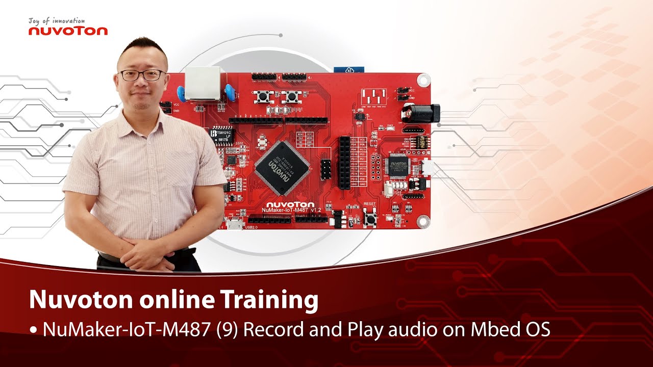
Hello everyone, I am Morgan, the principal engineer of Nuvoton Technology. Today, I will show you how to record and play audio with Mbed OS on NuMaker-IoT-M487 development board.
Open Chrome browser, and enter the URL https://ide.mbed.com to use the Mbed Online Compiler.
After log in, make sure that NuMaker-IoT-M487 board already selected in the upper right corner. If not, please refer Nuvoton IoT Tutorial series “Get Started with Mbed OS” which has a detailed description of how to add a board.
Click the “New” on the left of menu bar, a “Create new program” window will be displayed.
You can see that the Platform has been set to NuMaker-IoT-M487. In the Template, select the "NuMaker audio playback" for this tutorial. Then click OK.
Now you can see that the sample code has loaded on the page.
The sample code has three functions:
1. Record 10 seconds sound and save to Micro SD card
2. Play sounds stored in Micro SD card
3. Loopback. Record sound and play it immediately.
Click main.cpp to open it. Then scroll down to line 421. You can see the functions calls here. It set to loopback only.
Let’s do a little modification. Hit a key on console to start record 10 seconds then play it, and then do loopback.
printf("Press a key to start recording 10 seconds...");
getchar();
demo_record();
demo_play();
demo_loopback();
Save it and click “Compile” to build the code.
Compilation takes a while, please wait.
After the compilation is completed, “Success” will appear in the compile output window.
The browser downloads the binary firmware file directly after a successful compiling. It will be saved in a default download folder. In Chrome, you can click download file and select “Show in folder”.
Please plug an earphone commonly used for mobile phone in headphone jack on NuMaker-IoT-M487 board. For demonstration, we use a headphone splitter cable to connect a microphone and a speaker. Do not put the microphone and speaker too close to avoid feedback howling. Then connect the USB port to your computer and make sure the onboard LED lights up.
Back to the folder you just download the binary firmware file (NuMaker-mbed-AudioPlayback-example.NUMAKER_IOT_M487.bin). Drag and drop the file to NuMicro MCU drive.
You will see the copying progress dialog box.
Please find the virtual COM port assigned for NuMaker-IoT-M487 in Device Manager. In the demonstration, the “Nu-Link Virtual Com Port” is COMx.
Then use your favorite terminal tool. Here we use Putty. Open the COMx port with 9600 baud rate.
And no flow control settings. Then “Open” it.
Press “Reset” on board to run the firmware again.
Press a key on terminal to start record.
Speak for about 10 seconds, then your voice will be played.
That’s all for this tutorial. Thank you for watching.
Welcome to subscribe to our channel.
If you want to get more information, please contact us “SalesSupport@nuvoton.com”
-
For more information, please visit Nuvoton Technology Website: https://bit.ly/3hVdcmC
Buy now: https://direct.nuvoton.com/tw/numaker-iot-m487
Contact us: SalesSupport@nuvoton.com
#tool #training #learning #intermediate #en

Training
Tool
Learning
Watch time - 3:55
Hello everyone, I am Morgan, the principal engineer of Nuvoton Technology. Today, I will show you how to use SD card with Mbed OS on NuMaker-IoT-M487 development board.
Open Chrome browser, and enter the URL https://ide.mbed.com to use the Mbed Online Compiler.
After log in, make sure that NuMaker-IoT-M487 board already selected in the upper right corner. If not, please refer Nuvoton IoT Tutorial series “Get Started with Mbed OS” which has a detailed description of how to add a board.
Click the “New” on the left of menu bar, a “Create new program” window will be displayed.
You can see that the Platform has been set to NuMaker-IoT-M487. In the Template, select the "NuMaker SD-File-System with SD mode" for this tutorial. Then click OK.
Now you can see that the sample code has loaded on the page. LittleFS uses less memory, supports power failure protection. However, LittleFS is different from the FAT file system, so after uses littleFS, the SD card will be formatted as LittleFS. The sample code uses FAT file system as default.
Just click “Compiler” to build the example.
It is in compiling, please wait a moment.
After the compilation is complete, “Success” will appear in the compile output window.
The browser downloads the binary firmware file directly after a successful compiling. It will be saved in a default download folder or the folder based on your browser setting. In Chrome, you can click download file and select “Show in folder”.
Please insert a micro SD card into the card slot on the back of NuMaker-IoT-M487 board, then connect the USB to your computer and make sure the onboard LED lights up.
Let’s back to the folder you just download the binary firmware file (NuMaker-mbed-SD-FileSystem-example.NUMAKER_IOT_M487.bin). Drag and drop the file to NuMicro MCU drive.
You will see the copying progress dialog box.
Please find the virtual COM port assigned for NuMaker-IoT-M487 in Device Manager. In the demonstration, the “Nu-Link Virtual Com Port” is COMx.
Then use your favorite terminal tool. Here we use Putty. Open the COMx port with 115200 baud rate
And no flow control settings. Then “Open” it.
Press “Reset” on board to run the firmware again.
You can see the messages on terminal while accessing SD card.
That’s all for this tutorial. Thank you for watching.
Welcome to subscribe to our channel.
If you want to get more information, please contact us “SalesSupport@nuvoton.com”
-
For more information, please visit Nuvoton Technology Website: https://bit.ly/3hVdcmC
Buy now: https://direct.nuvoton.com/tw/numaker-iot-m487
Contact us: SalesSupport@nuvoton.com
#tool #training #learning #intermediate #en

Training
Tool
Learning
Watch time - 4:32
Hello everyone, I am Morgan, the principal engineer of Nuvoton Technology. Today, I will show you how to control the temperature and humidity sensor with Mbed OS on NuMaker-IoT-M487 development board. For this tutorial, we choose the “Thermo 6 Click” board. It is a mikroBUS board with a MAX31875 sensor. It is easy to install on NuMaker-IoT-M487 board because it has a mikroBUS connector. The part of control code refer from community, it is easy and quick to be integrated into real application.
Open Chrome browser, and enter the URL https://ide.mbed.com to use the Mbed Online Compiler.
After log in, make sure that NuMaker-IoT-M487 board already selected in the upper right corner. If not, please refer Nuvoton IoT Tutorial series “Get Started with Mbed OS” which has a detailed description of how to add a board.
Click the “New” on the left of menu bar, a “Create new program” window will be displayed. You can see that the Platform has been set to NuMaker-IoT-M487. In the Template, select the "NuMaker Thermo-Sensor MAX31875 " for this tutorial. Then click OK.
Now you can see that the sample code has loaded on the page. The sample code includes the MAX31875 control from community, declares an I2C object used on NuMaker-IoT-M487’s mikroBUS and a sensor object with the I2C object. Get the temperature value then print it. No modification needed, just click “Compile” to build the sample code.
It is in compiling, please wait a moment.
Then you can see the last message is “Success!” after compile completed.
The browser downloads the binary firmware file directly after a successful compiling. It will be saved in a default download folder or the folder based on your browser setting. In Chrome, you can click download file and select “Show in folder”.
Now is the time to install the Thermo 6 Click temperature and humidity sensor board on the mikroBUS, please pay attention to the correct orientation of the board.
Then we connect the NuMaker-IoT-M487 USB port to your computer and make sure the onboard LED lights up.
Let’s back to the folder you just download the binary firmware file (NuMaker-mbed-Sensor-MAX31875.NUMAKER_IOT_M487.bin). Drag and drop the file to NuMicro MCU drive.
You will see the copying progress dialog box.
Please find the virtual COM port assigned for NuMaker-IoT-M487 in Device Manager. In the tutorial, the “Nu-Link Virtual Com Port” is COMx.
Then use your favorite terminal tool. Here we use Putty. Open the COMx port with 115200 baud rate
And no flow control settings. Then “Open” it.
You can see the current temperature in Celsius and Fahrenheit printed on terminal.
That’s all for this tutorial. Thank you for watching. Welcome to subscribe to our channel. If you want to get more information, please contact us at SalesSupport@nuvoton.com
-
For more information, please visit: https://bit.ly/3hVdcmC
Buy now: https://direct.nuvoton.com/tw/numaker-iot-m487
Contact us: SalesSupport@nuvoton.com
#tool #training #learning #intermediate #en

Training
Tool
Learning
Watch time - 4:13
NuMaker-IoT-M487 (6) Use Ethernet
Hello everyone, I am Morgan, the principal engineer of Nuvoton Technology. Today, I will show you how to use Ethernet with Mbed OS on NuMaker-IoT-M487 development board.
Open Chrome browser, and enter the URL https://ide.mbed.com to use the Mbed Online Compiler.
After log in, make sure that NuMaker-IoT-M487 board already selected in the upper right corner. If not, please refer Nuvoton IoT Tutorial series “Get Started with Mbed OS” which has a detailed description of how to add a board.
Click the “New” on the left of menu bar, a “Create new program” window will be displayed. You can see that the Platform has been set to NuMaker-IoT-M487. In the Template, select the "NuMaker Ethernet TCP" for this tutorial. Then click OK.
Now you can see that the sample code has loaded on the page. The network default configuration is Ethernet, so we don’t have to manually modify mbed_app.json file. The sample code automatically acquires IP address, connects to web server and display the return message.
Just click “Compile” to build the sample code.
It is in compiling, please wait a moment.
Then you can see the last message is “Success!” after compile completed.
The browser downloads the binary firmware file directly after a successful compiling. It will be saved in a default download folder or the folder based on your browser setting. In Chrome, you can click download file and select “Show in folder”.
Connect the LAN cable in the network that does not require proxy settings. Then we connect the NuMaker-IoT-M487 USB port to your computer and make sure the onboard LED lights up.
Let’s back to the download folder where you can see the binary firmware file (NuMaker-mbed-tcp.NUMAKER_IOT_M487.bin). Drag and drop the file to NuMicro MCU drive.
You will see the copying progress dialog box.
Please find the virtual COM port assigned for NuMaker-IoT-M487 in Device Manager. In the tutorial, the “Nu-Link Virtual Com Port” is COMx.
Then use your favorite terminal tool. Here we use Putty. Open the COMx port with 115200 baud rate
And no flow control settings. Then “Open” it.
Press Reset button on board to run again.
You can see the connection messages printed on terminal. It shows the board’s IP address, sends a simple HTTP connection to server, and the result of return.
That’s all for this tutorial. Thank you for watching. Welcome to subscribe to our channel. If you want to get more information, please contact us at SalesSupport@nuvoton.com
-
For more information, please visit Nuvoton Technology Website: https://bit.ly/3hVdcmC
Buy now: https://direct.nuvoton.com/tw/numaker-iot-m487
Contact us: SalesSupport@nuvoton.com
#tool #training #learning #intermediate #en
Training
Tool
Learning
Watch time - 8:37
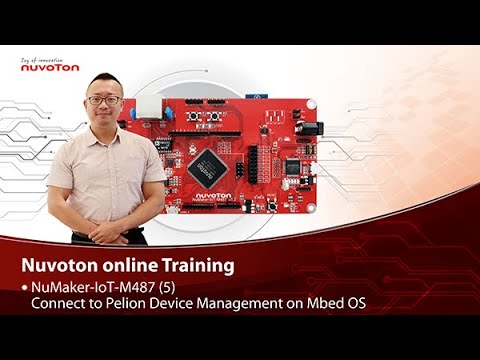
NuMaker-IoT-M487 (5)
Connect to Pelion Device Management on Mbed OS
Hello everyone, I am Morgan, the principal engineer of Nuvoton Technology. Today, I will show you how to connect to Pelion Device Management with Mbed OS on NuMaker-IoT-M487 development board.
Because the demonstration needs to store certificate, a MicroSD card is required.
Open Chrome browser, enter the URL https://cloud.mbed.com/quick-start
If you didn’t use Pelion Device Management before, you need to activate your Mbed account to access Pelion. Click the “Activate your free access”. Then log in your Mbed account.
Click “Activate Pelion Device Management account“…
Select the “Start the Connect Tutorial”
Then scroll down to select NuMaker-IoT-M487 (WiFi)
--After selected, scroll down and click “Get started”--
If you have completed previous tutorial, the NuMaker-IoT-M487 board has been selected in your Mbed account.
Please click the “2.2” to import the Pelion Connect Tutorial into your Online Compiler.
It shows the import dialog box, please click Import.
Wait for a moment while importing the sample code.
Click “mbed-os-example-pelion” project name,
Then click “Pelion Device Management” on menu bar, select “Manage Connect Certificates” in pull-down menu to create a Pelion certificate.
You need to provide API key. You can create a new one here.
Log in your mbed account.
Accept
Then click New API key
Assign an API Key name
Click Close
After created an API key, back to online compiler,
Then click Manage Connect Certificate again.
API Key automatically filled here.
Click OK.
Click “Create”, then assign a name for the certificate.
Click OK.
Click the certificate just created to select it, then click OK.
The online compiler will automatically update source code with the selected certificate.
Click “Pelion Device Management” on menu bar again, select “Apply Update Certificate”. An “Update Certificates” dialog box appears. Create it.
Click Download Private Key and save it.
Please make sure that NuMaker-IoT-M487 board already selected in the upper right corner. If not, please refer Nuvoton IoT Tutorial series “Get Started with Mbed OS” which has a detailed description of how to add a board.
In order to use Wi-Fi, you have to configure SSID and password to match your Wi-Fi access point setting.
In the mbed_app.json file, the default Wi-Fi security set to WPA and WPA2 in “nsapi.default-wifi-security” field. Please modify the field “nsapi.default-wifi-ssid” to your Wi-Fi SSID
Then modify “nsapi.default-wifi-password” to your Wi-Fi password.
Click on “Compile” to build it. Have to wait for a while.
Then you can see the last message is “Success!” at the bottom of this page.
The browser will download the binary firmware file directly after a successful compiling. It will be saved in a default download folder or the folder based on your browser setting. In Chrome, you can click download file and select “Show in folder”.
Then we connect the NuMaker-IoT-M487 USB port to your computer and make sure the onboard LED lights up.
Let’s back to the download folder where you can see the binary firmware file (mbed-os-example-pelion.NUMAKER_IOT_M487.bin). Drag and drop the file to NuMicro MCU drive.
You will see the copying progress dialog box.
Please find the virtual COM port assigned for NuMaker-IoT-M487 in Device Manager. In the tutorial, the “Nu-Link Virtual Com Port” is COMx.
Then use your terminal tool. Here we use Putty. Open the COMx port with 115200 baud rate, 8 bits, 1 stop bit, none parity, and no flow control settings.
Then “Open” it.
Press Reset button on board to run again.
You can see the connection messages printed on terminal. It shows the board’s IP address obtained from the Wi-Fi access point, and the Endpoint Name.
Then you can see the device resource in Pelion Device Management Portal.
Log in Pelion Portal with the same Mbed account.
Click Device directory. Find the device ID which should be registered state.
Click the Device ID, it shows the Device details.
Click RESOURCES, find the resource 3200/0/5501. Click the resource.
Now, you can press keys in terminal to increase the counter. Or the counter automatically increase 1 by one second. The demo code also updates the counter to Pelion. You will see the value change in the graph.
That’s all for this tutorial. Thank you for watching. Welcome to subscribe to our channel. If you want to know more information, please contact us at SalesSupport@nuvoton.com
-
For more information, please visit Nuvoton Technology Website: https://bit.ly/3hVdcmC
Buy now: https://direct.nuvoton.com/tw/numaker-iot-m487
Contact us: SalesSupport@nuvoton.com
#tool #training #learning #intermediate #en