Search
Search Results
SearchSample code ,
find 35 items
- Sort by
- Most recent
- Popularity

Product
Tool
Learning
Watch time - 8:24
The video introduces Nuvoton's MPU N9H30's development set-up for Linux and Non-OS, taking NuMaker-emWin-RDK-N9H30 for example. Starting from the EVB introduction to BSP and related software downloads.
-
User manuals and related resource can be downloaded
https://www.nuvoton.com/products/gui-solution/gui-reference-design/numaker-emwin-rdk-n9h30/
First, we introduce how to program Linux OS to the N9H30 evaluation board
Find the N9H30 evaluation board resource that we used on Nuvoton’s Github and download the VMware Image
https://github.com/OpenNuvoton/MPU-Family
VMware application can be downloaded from the VMware website
https://www.vmware.com/tw/products/workstation-player/workstation-player-evaluation.html
First, open the VMware
Find the ubuntu_NUC970_980_Linux folder we downloaded
Choose Ubuntu 64-bit_nuvoton.vmx
Choose Play virtual machine
The password is “user”
It will take a while to open this application for the first time
Open the terminal when the system is ready
Enter NUC970_Buildroot-master folder
After entering the folder, we need to update the Buildroot tool
Enter the command as shown below
“git reset –hard”
“git pull”
After updating, enter the dl folder
Remove the original Linux kernel and u-boot
Enter the command as shown below
“sudo rm -rf linux-master.tar.gz uboot-master.tar.gz”
After entering, enter the password “user”
Leave the dl folder and enter the Buildroot folder
Enter the “make clean” command
You don’t need to do these steps unless updating Buildroot tools
Now, we set up the evaluation board configuration
Enter configs folder to search evaluation board name
Back to buildroot after searching
Enter “make nuvoton_n9h30_emwin_defconfig” to generate configuration file
After finishing these step, enter “make” to compile
It will take about three hours to compile
After compiling, copy the two files below to windows
“/NUC970_Buildroot-master/output/images/uImage”
“/NUC970_Buildroot-master/output/build/uboot-master/u-boot.bin”
Create text file ”env-nor.txt”
The content is shown below:
baudrate=115200
bootdelay=1
stderr=serial
stdin=serial
stdout=serial
setspi=sf probe 0 50000000
loadkernel=sf read 0x7fc0 0x200000 0x600000
bootcmd=run setspi;run loadkernel;bootm 0x7fc0
bootargs=noinitrd root=/dev/mtdblock2 rw rootfstype=jffs2 console=ttyS0 rdinit=/sbin/init mem=32M mtdparts=m25p80:0x200000@0x0(u-boot),0x600000@0x200000(kernel),-(user) ignore_loglevel
Then, we need to install NuWriter and related file
The NuWriter is a programming tool provided by Nuvoton. The NuWriter application and firmware code are open-sourced, and users can add new features or develop new user interfaces per user’s application
NuWriter: https://github.com/OpenNuvoton/MPU-Family
Open “NUC970_NuWriter-master”
Enter Driver folder and install “WinUSB4NuVCOM.exe”
Enter /Nuwriter/Release and execute NuWriter
Choose IC number based on the evaluation board
We need to program Image to SPI Flash, so we choose SPI
Here we need to turn the all Power-On Setting to ON
Push Reset button
Return to NuWriter to check the green light and the connection
If it is not connecting, click Re-Connect to reconnect
After confirm the connection, start to program Image
Program the three files to particular address
u-boot.bin program to 0xe00000
env.nor.txt program to 0x80000
uImage program to 0x200000
After programming, turn the Power-On Setting to off
Push the Reset button
Evaluation board can start to boot from SPI-NOR
After booting, we need to find the rcS demo application under/etc/init.d
Enter “chmod 777 rcS” to modify the application
Now, you can see the application on the evaluation board panel
Here, we finish compiling and programming
The next topic is how to compile and program Non-OS code
First, download MDK-Arm from the link below
https://www.keil.com/download/product/
Download the Non-OS BSP provided by Nuvoton
https://github.com/OpenNuvoton/MPU-Family
The BSP includes Keil environment set up user manual
Use Keil need to purchase the related license
After downloading, Open Keil uVision
Click the File on the upper left and choose Open
Go to the BSP that we downloaded choose BSP, SampleCode, emWin_SimpleDemo, KEIL and emWin_SimpleDemo.uvproj
Click Option for Target
Click Device and choose NuMicro ARM9 Database and N9H_series
After setting up, click Rebuild, and it will generate a sample code application which is a binary file
Open the NuWriter and connect it to the evaluation board
Choose SPI and search the application we built
\N9H30_emWin_Non-OS_BSP_v1.04.000\N9H30_emWin_Non-OS_BSP_v1.04.000\BSP\SampleCode\emWin_SimpleDemo\KEIL\obj\emWin_SimpleDemo_FW070TFT_24BPP.bin
Follow the setting and program the file to 0x0
After programming, turn the Power-On Setting to boot from SPI
You can see the demo application on the evaluation
#Basic #Product #Tool #Learning #en
-
For more information, please visit Nuvoton Technology Website: https://bit.ly/3hVdcmC
buy now: https://direct.nuvoton.com/
contact us: SalesSupport@nuvoton.com

Watch time - 10:23
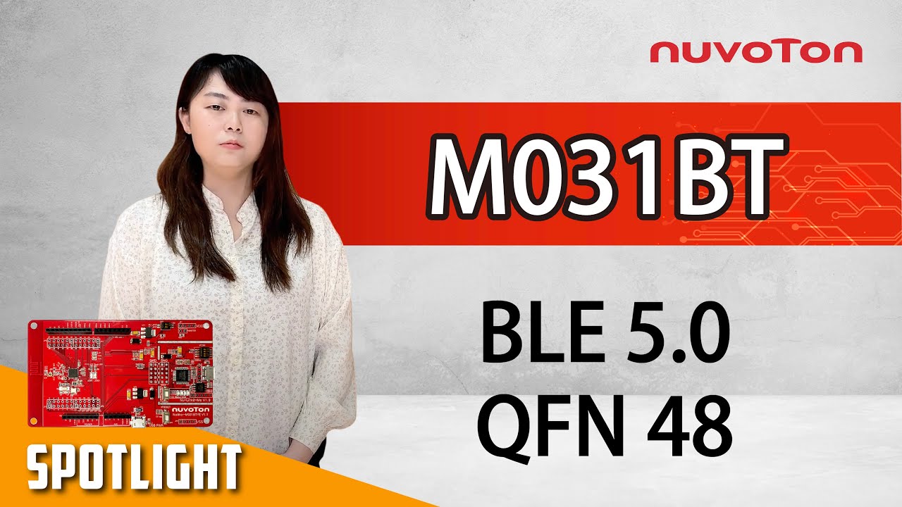
新唐 NuMicro M031BT 雙模藍牙低功耗 5.0 (Bluetooth Low Energy, BLE5.0) 提供了 BLE UART 透傳的展示,並實際操作如何使用 AT 命令模式來作設定與使用資料傳輸模式來收發資料。
-KEIL MDK Nuvoton edition M0/M23(Free License)
https://www2.keil.com/nuvoton/M0-M23
-Nu-Link_Keil_Driver
https://www.nuvoton.com/resource-download.jsp?tp_GUID=SW1120200221180521
-M031 BLE AT Command User Guide:
M031_Series_BSP_CMSIS_V3.xx.xxx\SampleCode\NuMaker-M03xBT_XXXXXX\BLE\Doc\M031 BLE AT Command User Guide.pdf
-Related sample codes in the BSP (Board Support Package)
BSP_ Library\M031_Series_BSP_CMSIS_V3.xx.xxx\SampleCode\NuMaker-M03xBT_xxxxxx\BLE\Demo
ATCMD
-App
App Store (Apple devices)
https://apps.apple.com/tw/app/nuvotonble/id1514073524
Google Play Store (Android devices)
https://play.google.com/store/apps/details?id=com.nuvoton.nuble
大家好,我是新唐的工程師Oliver,今天爲大家介紹M031BT的BLE UART透傳範例程式的展示,另外也會簡單介紹一下M031BT的特點。
M031BT的特點是它是一個有豐富周邊且帶有BLE 5.0無線傳輸的MCU,在系統方面CPU可以運行到48MHz,Flash最多可達128 KB,SRAM最多可達16KB,封裝是QFN 5x5mm,在48 pin的IC中算是非常小的,在類比周邊部分ADC是12-bit且采樣速度可以高達2 MSPS,另外還有2組比較器;數位周邊也非常的豐富,像是UART有3組、I2C有2組、PWM有12通道,且PWM解析度可以高達2倍的系統頻率96 MHz、Timer有4個;在無線傳輸部分支援BLE 5.0或2.4G私有協議,可調整的發射功率可達+8 dBm,接收靈敏度可達 -94 dBm
新唐對於藍牙的開發支援了透傳/HOGP/heatbeat三種profile並且有OTA功能,此外central mode/peripheral mode的切換功能,有更多元場景應用的可能性,對於不熟悉藍牙開發的客戶我們也支援AT command協助客戶可以快速開發,透過新唐所推出的M031BT您可以應用在個人醫療儀器、個人保健照護、量測儀器或是智慧門鎖等應用
接下來介紹今天demo的BLE UART透傳,在demo的系統中會有個HOST透過UART傳資料給M031BT,M031BT再經由BLE將資料傳送給手機,或由手機發資料透過BLE傳送到M031BT,再由M031BT的UART傳給HOST,再這個dome中分爲兩種模式一種是AT Command,是用來對M031BT做基本設定,另一種模式是資料傳輸模式也就是透傳模式,M031BT會將UART收到的資料轉爲BLE送出去,或將BLE收到的資料轉爲UART再給HOST,這兩種模式的切換是透過HOST控制高低准位並且輸入到M031BT的GPIO來切換
在開始測試之前我們需要先準備測試環境,我們使用NuMaker-M031BTYE一台電腦當作HOST,NuMaker-M031BTYE上的Nu-Link2-Me當作USB轉UART的橋接器,M031BT的UART脚位PA0/PA1會經由VCOM switch連接到Nu-Link2-Me
的UART引脚,我們只要把VCOM指撥開關的Pin1/Pin2撥到ON就可以連接
另外M031BT的模式控制脚位PB0若連接到VDD是AT command 模式,若連接到GND是資料傳輸模式,模式控制脚位預設內部上拉至VDD,所以預設是AT command 模式
現在我們將USB線接上NuMaker與電腦後,開啓裝置管理員確認com port是否有連接上,確認是COM3就可以關掉了,接著電腦上需要安裝任一種的串列通訊軟體,影片中我們使用Putty當作範例,安裝完Putty之後,開啓Putty選擇Serial,輸入剛剛確認的COM3還有115200的波特率,按下OPEN
再來我們需要將AT Command的固件下載到M031BT,我們開啓ATCMD這個範例的專案,按下編譯,編譯完之後按下載等待下載完成,下載完成後我們可以看到Putty的視窗中已經有打印出一些信息了,代表燒錄成功
再來是如果安卓裝置要在Google Play Store下載App若是iOS的話要在App Store下載後安裝,影片中以安卓來當作範例,開啓Paly Store並輸入Nuvoton BLE看到後點選安裝,等安裝完成後初步的環境設置就算完成了
接著來看看ATCMD支援的命令有哪些,這是AT command 的列表,主要都是用來查看M031BT的參數或是設定M031BT的參數
例如輸入AT是測試命令,查看M031BT在AT command模式是否正常;
輸入AT+HELP? 是查看支援那些命令;
輸入AT+UART是察看UART波特率是多少,預設是115200,也可以設定波特率,目前支援五種不同的波特率;
AT+NAME可以看裝置名稱或修改裝置名稱;
AT+ADVINT可以查看目前的廣告間隔時間與設定廣告間隔時間;
AT+ADVEN可以開啓廣告,讓手機可以搜尋的到,要注意的是預設沒有開的AT+TXPWR可以設定輸發射功率,目前有三種段數可設定,分別是0/4/8 dBm; AT+SLEEP可以讓M031BT沒發送資料時候進入睡眠模式,節省功耗
其他詳細說明可以參考這份表格或M031 BLE AT Command User Guide這份文件,這個文件在BSP裏面可以找到
接下來我們來實際操作,這一頁說明ATCMD這個範例程式的預設參數設定,像是波特率是115200,發射功率是+8 dBm,大家可以參考一下。
我們先前開啓過裝置管理員確認設定是COM3還有波特率是115200,接著NuMaker-M031BTYE的reset 按鍵,就可以看到M031BT AT Command的字顯示在PuTTY的視窗中,那預設模式脚位的PB0預設是上拉到VDD,所以預設是AT command 模式
接著使用鍵盤輸入AT按下enter按鍵,若出現OK代表AT command 模式是正常,即可輸入其他指令
若要查看支援那些指令,可以輸入AT+HELP?再按下enter鍵,就會出現全部支援的指令有哪些
若要看現在的波特率設定輸入AT+UART? 再按下enter鍵,就可以知道UART目前的波特率
廣告的間隔時間可以查看也可以修改,輸入AT+ADVINT? 就可以得到目前的廣告間隔時間,看到目前是160,這個數值每個單位是0.625us,也就是100ms,間隔時間的設定會影響到平均的功耗,這時間也可以修改,間隔時間越長平均功耗越低,不過也是要看應用需要多少時間
再來我們輸入AT+ADVINT=320可以看到回復OK,代表時間已經改爲200ms,我們可以再次輸入AT+ADVINT?得到間隔時間是320,確認修改成功
輸入AT+ADVEN可以開啓廣告讓手機可以搜尋的到,預設並沒有開啓,所以輸入開啓的指令
輸入AT+ADDR?可以查詢BLE設備位址
再來我們可以輸入AT+NAME?來查詢BLE設備的名稱,我們可以看到裝置名稱是NVT-M031BT,
打開手機的APP來搜尋看看,搜尋到的就是NVT-M031BT
那也可以修改BLE設備的名稱,只要依據前面的表格下指令就可以
再來是數據傳輸模式演示,也就是透傳模式,我們首先再AT command模式下輸入AT+ADVEN啓用廣告可讓手機搜尋的到,再來開啓NuBLE掃描並連接到NVT-M031BT,接著我們必須要手動將模式控制引脚PB0如畫面上的連接到GND,就可以切換成爲數據傳輸模式也就是透傳模式
再來我們在文字輸入欄位中輸入字符串,然後點擊SEND按鍵,那麽手機上輸入的資料就會透過BLE傳送資料到M031BT,M031BT再將收到的資料經由UART透過Nu-Link2-Me傳送到PC的終端窗口中
剛剛已經演示過兩種模式的使用方式,在相關資源部分
基本的開發環境KEIL我們提供的免費許可證,依照連結網頁內的步驟來做只要使用新唐的M0/M23 MCU就可以免費使用,另外Nu-Link的driver也提供連結下載
另外關于影片中的M031 BLE AT Command用戶指南已經放入BSP內,裏面有更詳細的操作與說明,BSP可從官網下載,APP部分也附上連結,方便大家使用
以上是這次的教學影片,感謝您的收看。歡迎訂閱我們的頻道。
如果您想知道更多資訊歡迎聯絡我們!
-
更多產品資訊,請至新唐科技網站 https://bit.ly/3hVdcmC
購買管道:https://direct.nuvoton.com/tw
聯絡我們:SalesSupport@nuvoton.com

Product
Application
Learning
Watch time - 2:24
Hello everyone. Welcome back to Nuvootn’s YouTube channel. This is a reference design of a thermostat made by Nuvoton. The first screen shows the current room temperature of 25 degrees Celsius. You can also set your target temperature through the control panel. The middle switch is the power switch of temperature control. Press the Temperature icon and you can adjust backlight brightness by slide control.
Back to the function page, press the Snow icon where you can change the strength of the air conditioner. You can increase or decrease the strength by these up and down arrows or you can press the snow icon for adjustment. Changing the heater, dehumidifier, and fan are the same. The third page is a calendar where you can set the date to book opening and closing the temperature control. What you saw is the reference design introduction.
Now let’s talk about the composition of the board. In the middle of the board is a Nuvoton N9H20 main control chip. This main control chip has built-in 32 Mbytes DDR so the board is very clear and the hardware design is easy. At the top side, there is a 1 Gbits NAND Flash for code and pictures storage. At the bottom left there is a connector to the UART control interface. In the middle left area, there is a 5 Voltage (Micro USB) power input. In the upper right corner, there is an RS485 connection. Through this green connector, you can connect to RS485 for fans, air conditioners, and other devices' control. In the lower right corner, there is a chip for power IC and some other parts. The application reference design is concise and powerful. That’s all for the hardware introduction. Thank you for watching.
-
For more information, please visit Nuvoton Technology Website: https://bit.ly/3hVdcmC
buy now: https://direct.nuvoton.com/tw/
contact us: SalesSupport@nuvoton.com
#Product #Application #Learning #Intermediate #en
Watch time - 2:41
NuMicro® M031BT BLE 5.0 低功耗藍牙微控制器系列,以 Arm® Cortex®-M0 為核心,工作頻率高達 48 MHz,內建最高 128 KB Flash 和 16 KB SRAM,提供 BLE 5.0 和 2.4 GHz 雙模功能。相較於傳統集成簡單周邊的 BLE SoC,NuMicro® M031BT 系列內建豐富周邊與優異類比控制功能,實現一顆微控制器取代 BLE SoC 加控制晶片的方案,不僅大幅縮小 PCB 尺寸,QFN48封裝面積僅有 5mm x 5mm,也降低射頻佈局困難度,加上新唐參考設計方案與範例代碼,使得低功耗藍芽的應用開發變得相當容易。
NuMicro® M031BT 系列針對射頻應用提供高達 +8 dBm 的射頻發射功率、-94 dBm 的良好接收靈敏度、1 Mb/s 或 2 Mb/s 的傳輸速度,並且能在 2.4GHz 干擾嚴重的環境提供突出的抗噪表現,提升通訊距離和可靠性,滿足智慧家庭、消費電子以及工業物聯網等應用場景的需求。
NuMicro® M031BT 系列運作於 1.8V 至 3.6 V 工作電壓,內建 32 位硬體乘法器/除法器、高達 5 通道 PDMA、16 通道 12 位2 MSPS 高採樣率的 ADC 可運行在 1.8V 低電壓,提供精確且快速地效能表現,12 路 96 MHz PWM 可快速響應和精準的控制外部裝置。此外,M031BT 亦提供了豐富的周邊,例如 1 組 24 MHz SPI/I2S、3 組 6 MHz UART 並可支援單線式傳輸、2 組 I2C、1 組高彈性通用串行控制接口 (USCI) 可設為 UART, I2C 或 SPI。
NuMicro® M031BT 系列為了保護開發者的智慧財產權,內嵌一個額外的安全保護 Flash 區塊 (SPROM, Security Protection ROM),提供一個獨立且安全加密執行區域以保護關鍵程式代碼。記憶體鎖定功能 (Flash lock bits) 設計提供韌體防止外界存取或寫入保護。每一顆M031BT 具有一個 96 位元晶片唯一序號 (Unique Identification, UID) 及一個 128 位元唯一客戶序號 (Unique Customer Identification, UCID),大幅提升產品的保密與代碼安全性。
NuMicro® M031BT series: An low-power BLE 5.0 and 2.4GHz dual-mode microcontroller series by Arm® Cortex®-M0 core operating up to 48 MHz, with up to 128 KB Flash and 16 KB SRAM. In addition to the BLE 5.0 and 2.4GHz RF functions, the NuMicro® M031BT series built-in rich peripherals and analog control functions realize wireless connectivity. The 5mm x 5mm QFN48 package greatly reduces the PCB size and reduces RF layout difficulty. Furthermore, Nuvoton's reference design and rich sample code make the application development for low-power microcontroller with BLE/2.4G RF easier.
The NuMicro® M031BT series provides up to +8 dBm RF transmit power, a good receiving sensitivity of -94 dBm, 1 Mb/s, or 2 Mb/s transmission speed RF applications, and outstanding anti-noise performance in 2.4GHz interference environments to ensure communication distance and reliability. With these, the M031BT series are expected to meet the needs of application scenarios such as industrial Internet of Things (IIoT), smart home, consumer electronics, etc.
The NuMicro® M031BT series operates from 1.8V to 3.6V. It features a built-in 32-bit hardware divider, up to 5-channel PDMA, a 16-channel 12-bit 2 MSPS high sampling rate ADC that can run down to 1.8V low voltage, and 12-channel PWM running up to 96 MHz that can quickly respond and accurately control external devices. Besides, the M031BT also provides many peripherals such as one set of 24 MHz SPI/I2S, three sets of 6 MHz UART supporting single-wire transmission, two sets of I2C, and one set of highly flexible universal serial control interface (USCI) that can be configured as UART, I2C or SPI.
To protect the intellectual property rights, the NuMicro® M031BT series is embedded with an additional security protection Flash block (Security Protection ROM, SPROM) to provide an independent and secure encrypted execution area to protect critical program code. Flash lock bits are designed to provide firmware to prevent external access or write protection. There is a 96-bit unique chip identification (Unique Identification, UID) and a 128-bit unique customer identification (UCID) on each M031BT, which significantly improves product confidentiality and code security.
Nuvoton provides complete development tools, such as the NuMaker-M031BT evaluation board, software development kits, and sample codes, as well as free downloadable Keil MDK to speed up the end-product evaluation and development cycle.
-
更多產品資訊,請至新唐科技網站 https://bit.ly/3hVdcmC
購買管道:https://direct.nuvoton.com/tw
聯絡我們:SalesSupport@nuvoton.com

Training
Tool
Learning
Watch time - 4:14
The video will introduce you the NuMicro™ Family M251/M252 Series BSP, includes how to download the BSP and introduction of each sample codes and folders. And help you use the template to develop your first M251/M252 program.
#Tool #Training #Learning #Intermediate #en
-
For more information, please visit Nuvoton Technology Website: https://bit.ly/3hVdcmC
Buy now: https://direct.nuvoton.com/numaker-m251sd
Contact us: SalesSupport@nuvoton.com

Training
Tool
Learning
Watch time - 6:27
#Tool #Training #Learning #Intermediate #en
-
For more information, please visit Nuvoton Technology Website: https://bit.ly/3hVdcmC
Buy now: https://direct.nuvoton.com/numaker-m251sd
Contact us: SalesSupport@nuvoton.com

Training
Tool
Learning
Watch time - 2:21
Hello everyone! I am Chris, the Field Application Engineer from Nuvoton Technology.
Today, I will introduce how to run a simple sample code on NuMicro M251/M252 series microcontroller.
First, we connect the M251/M252 NuMaker development Board to the computer.
Then click the M251/M252 BSP folder, click the Sample Code folder, template folder, Keil folder, and finally open the Template project file.
What we are going to do is running a simple GPIO Toggle LED Sample Code.
Introduce the main program briefly.
First, set GPIO PB14 to Output Mode.
After writing a small loop, set PB14 to reverse.
Finally, set CLK_SysTickDelay to 300,000 microseconds (uSec).
Before Rebuild, we must add the GPIO Source Code to the Library, find the corresponding Source Code and load it, and press Rebuild after it is complete. After the Rebuild, press Load and program the Code into the IC.
When programing is over, press the reset button on the development board to confirm whether the LED lights are flashing on the board.
That’s all for the tutorial of running sample code. Thank you for watching it. If you want to know more information, please feel free to contact us.
#Tool #Training #Learning #Intermediate #en
-
For more information, please visit Nuvoton Technology Website: https://bit.ly/3hVdcmC
Buy now: https://direct.nuvoton.com/numaker-m251sd
Contact us: SalesSupport@nuvoton.com

Training
Tool
Learning
Watch time - 3:24
Hello everyone I am Chris, the Field Application Engineer from Nuvoton Technology.
Today I will introduce the programming and debugging tool, called NuLink-Gang, and NuLink2-Pro. And I will show you in what kind of situation you can utilize the tools.
During system development, Nuvoton provides three IDE interfaces: KEIL, IAR, and NuEclipse for user to develop source code.
When programming the Chip, Nuvoton provides ICP programming Tool in PC and the debugger Nu-Link2-Pro for users to perform debugging and programming function.
User who uses all of the Nuvoton Nu-Maker boards series can develop through the Nu-Link2-Me debugger and programmer; it’s attached to the board.
During the mass-production stage, there are 2 modes for programming the target chip. One is online programming and the other is offline programming.
At first, in online programming mode, user can use ICP programming Tool and a Nu-Link2-Pro to program a target chip. Besides, if it needs to program several chips at one times, the Nu-Link Command Tool supports program multiple develop board by several Nu-Link2-Pro.
Nu-Link2-Pro also supports drag-and-drop Flash programming. User can intuitively complete the programming action.
Nu-Link2-Pro
In offline programming mode, user can pre-store the programming file in SPI flash, USB flash drive, or SD card. When user wants to program the target chip, pressing the programming button on Nu-Link2-Pro to complete the programming action.
If it needs a large number of ICs to be programming, it recommends using the Nu-Link-Gang programmer. Nu-Link-Gang programmer can perform offline programming on four different chips at a time, significantly increasing the programming efficiency. Besides, Nu-Link-Gang programmer can also use the control bus to connect with an automatic programming machine for automatic programming.
In the system upgrade, Nu-Link2-Pro also provides five standard communication interfaces such as SPI, I2C, UART, RS485, and CAN for transmission, which is convenient for users to upgrade the system.
That’s all for the introduction of Nuvoton’s programming and debugging tool, NuLink-Gang, and NuLink2-Pro. Thank you for watching it. If you want to know more details, please contact us! Thank you.
#Tool #Training #Learning #Intermediate #en
-
For more information, please visit Nuvoton Technology Website: https://bit.ly/3hVdcmC
Buy now: https://direct.nuvoton.com/numaker-m251sd
Contact us: SalesSupport@nuvoton.com

Training
Tool
Learning
Watch time - 5:9
Hello everyone, I am Chris, the field application engineer from Nuvoton Technology. Today, I will introduce the application and principle of programmable seriel I/O aka PSIO on M251/M252.
The programmable serial I/O of NuMicro M251/M252 series can generate arbitrary waveforms and combine them to achieve data transmission and reception of specific serial communication protocols.
Of course, standard serial communication can also be achieved, such as UART SPI I2C
Usually, it is common to use Timer+GPIO to achieve these specific communication protocols, but it is more complicated and requires frequent CPU intervention.
When we use PSIO, this not only simplifies the complexity of the operation but also reduces the burden on the CPU. The saved CPU performance could be distributed in other places.
Since all hardware operations do not require software intervention, the timing control is more precise.
The principle of PSIO is to use a slot controller to control the pin input and output or determine the state, and it can also control the duration of these states.
Each slot controller has eight slots, which can be used as eight settings, and the registers corresponding to each slot can access the data that needs to be input and output, and can also set the time for the current pin to maintain this state.
Each slot can reach a checkpoint, usually 1 to 1, 2 to 2, 3 to 3, and so on. Each checkpoint can set the pin status of the corresponding slot within the corresponding time.
Next, let’s take a look at a simple output-only example
In the initial stage, we first set the state of the pin to be high before SLOT has started, so the output is high
Then when the Slot controller receives the start signal, SLOT0 is set to output low level according to the setting of CP0 and waits for the time of SLOT0 to expire.
Then SLOT1 is set to output low level according to the setting of CP1 and waits for the time of SLOT1 to expire.
And so on, followed by SLOT2 output low level
SLOT3 low level
SLOT4 high level
SLOT5 high level
After SLOT5, since SLOT6 is not set, the waveform of the protocol can be completed with only six slots
Between the time of the next data transmission, we set the interval low, so the output is low at this time
Users can complete different protocols according to these simple operations.
In the related resources section, we have provided two PSIO application notes. There are two protocol examples with more detailed operations and descriptions. If you want to know more details about PSIO, please download it from the URL in the video.
Several sample codes of different protocols are also provided in BSP.
That’s all for this tutorial. Thank you for watching it. Welcome to subscribe to our channel. If you want to know more information, please contact us.
#Tool #Training #Learning #Intermediate #en
-
For more information, please visit Nuvoton Technology Website: https://bit.ly/3hVdcmC
Buy now: https://direct.nuvoton.com/numaker-m251sd
Contact us: SalesSupport@nuvoton.com

Training
Tool
Learning
Watch time - 5:53
Hello everyone, I am Morgan, the principal engineer of Nuvoton Technology. Today, I will show you how to connect to AWS IoT service using MbedOS on NuMaker-IoT-M487 development board
The sample code is on GitHub, the URL is https://github.com/OpenNuvoton/Mbed-to-AWS-IoT
To avoid typos, use keyword “OpenNuvoton” to search on google.
Find the Nuvoton on GitHub, and click it
On the Nuvoton GitHub page, use AWS as keyword to search the sample code: Mbed-to-AWS-IoT
Right click to copy the URL for later use.
Then enter the URL https://ide.mbed.com
After log in, make sure the NuMaker-IoT-M487 board has selected in the upper right corner. If not, please refer Nuvoton IoT Tutorial series “Get Started with Mbed OS”. There is detailed description of how to add a board.
Click the “Import” on the left of menu bar.
In the “Import Wizard”, click “Click here”
Please paste or key in the sample code URL to “Source URL:”,
Select Import as “Program”
Click “Import Name”, the project name “Mbed-to-AWS-IoT” will be filled automatically.
Then click “Import”.
After sample code imported, click “mbed_app.json” to open it.
To use Wi-Fi, you have to configure SSID and password to match your Wi-Fi AP setting.
In NuMaker_IOT_M487 session of mbed_app.json file, find the “wifi-ssid” to set your SSID. It is at line 44.
And then set password to “wifi-password”. It is at line 45.
Save it and click “Compile” to build the code.
It takes time to compile code, please wait.
You need an AWS account to use AWS IoT Core service. To create a thing, a policy, and certificates, then put the certificate to MQTT_server_setting.h file in the sample code. The sample code has included a certificate provided by Nuvoton for test only, so that you can quickly operate this example. If you don’t have an AWS account, it is recommended that you apply for an account and use your certificates in the example to observe the connection status on AWS IoT console page.
After completed, “Success” will appear in the compile output window.
The browser downloads the binary firmware file directly after a successful compiling. It will be saved in a default download folder. In Chrome, you can click download file and select “Show in folder”.
Then we connect the NuMaker-IoT-M487 USB port to your computer.
Please find the virtual COM port assigned for NuMaker-IoT-M487 in Device Manager. In the tutorial, the “Nu-Link Virtual Com Port” is COMx.
Then use your favorite terminal tool. Here we use Putty. Open the COMx port with 115200 baud rate.
And no flow control settings. Then “Open” it.
Back to the folder you just download the binary firmware file (Mbed-to-AWS-IoT.NUMAKER_IOT_M487.bin). Drag and drop the file to NuMicro MCU drive.
You will see the copying progress dialog box.
You can see the messages on terminal.
The device has acquired IP address from Wi-Fi AP, then successfully connect to AWS IoT and subscribe a topic.
Then press button (SW2) on board to send a message.
You can see the message published to server and received a message from server.
That’s all for this tutorial. Thank you for watching.
Welcome to subscribe to our channel.
If you want to get more information, please contact us “SalesSupport@nuvoton.com”
-
For more information, please visit Nuvoton Technology Website: https://bit.ly/3hVdcmC
Buy now: https://direct.nuvoton.com/tw/numaker-iot-m487
Contact us: SalesSupport@nuvoton.com
#tool #training #learning #intermediate #en
Training
Tool
Learning
Watch time - 5:0
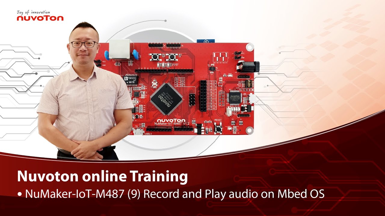
Hello everyone, I am Morgan, the principal engineer of Nuvoton Technology. Today, I will show you how to record and play audio with Mbed OS on NuMaker-IoT-M487 development board.
Open Chrome browser, and enter the URL https://ide.mbed.com to use the Mbed Online Compiler.
After log in, make sure that NuMaker-IoT-M487 board already selected in the upper right corner. If not, please refer Nuvoton IoT Tutorial series “Get Started with Mbed OS” which has a detailed description of how to add a board.
Click the “New” on the left of menu bar, a “Create new program” window will be displayed.
You can see that the Platform has been set to NuMaker-IoT-M487. In the Template, select the "NuMaker audio playback" for this tutorial. Then click OK.
Now you can see that the sample code has loaded on the page.
The sample code has three functions:
1. Record 10 seconds sound and save to Micro SD card
2. Play sounds stored in Micro SD card
3. Loopback. Record sound and play it immediately.
Click main.cpp to open it. Then scroll down to line 421. You can see the functions calls here. It set to loopback only.
Let’s do a little modification. Hit a key on console to start record 10 seconds then play it, and then do loopback.
printf("Press a key to start recording 10 seconds...");
getchar();
demo_record();
demo_play();
demo_loopback();
Save it and click “Compile” to build the code.
Compilation takes a while, please wait.
After the compilation is completed, “Success” will appear in the compile output window.
The browser downloads the binary firmware file directly after a successful compiling. It will be saved in a default download folder. In Chrome, you can click download file and select “Show in folder”.
Please plug an earphone commonly used for mobile phone in headphone jack on NuMaker-IoT-M487 board. For demonstration, we use a headphone splitter cable to connect a microphone and a speaker. Do not put the microphone and speaker too close to avoid feedback howling. Then connect the USB port to your computer and make sure the onboard LED lights up.
Back to the folder you just download the binary firmware file (NuMaker-mbed-AudioPlayback-example.NUMAKER_IOT_M487.bin). Drag and drop the file to NuMicro MCU drive.
You will see the copying progress dialog box.
Please find the virtual COM port assigned for NuMaker-IoT-M487 in Device Manager. In the demonstration, the “Nu-Link Virtual Com Port” is COMx.
Then use your favorite terminal tool. Here we use Putty. Open the COMx port with 9600 baud rate.
And no flow control settings. Then “Open” it.
Press “Reset” on board to run the firmware again.
Press a key on terminal to start record.
Speak for about 10 seconds, then your voice will be played.
That’s all for this tutorial. Thank you for watching.
Welcome to subscribe to our channel.
If you want to get more information, please contact us “SalesSupport@nuvoton.com”
-
For more information, please visit Nuvoton Technology Website: https://bit.ly/3hVdcmC
Buy now: https://direct.nuvoton.com/tw/numaker-iot-m487
Contact us: SalesSupport@nuvoton.com
#tool #training #learning #intermediate #en

Training
Tool
Learning
Watch time - 3:55
Hello everyone, I am Morgan, the principal engineer of Nuvoton Technology. Today, I will show you how to use SD card with Mbed OS on NuMaker-IoT-M487 development board.
Open Chrome browser, and enter the URL https://ide.mbed.com to use the Mbed Online Compiler.
After log in, make sure that NuMaker-IoT-M487 board already selected in the upper right corner. If not, please refer Nuvoton IoT Tutorial series “Get Started with Mbed OS” which has a detailed description of how to add a board.
Click the “New” on the left of menu bar, a “Create new program” window will be displayed.
You can see that the Platform has been set to NuMaker-IoT-M487. In the Template, select the "NuMaker SD-File-System with SD mode" for this tutorial. Then click OK.
Now you can see that the sample code has loaded on the page. LittleFS uses less memory, supports power failure protection. However, LittleFS is different from the FAT file system, so after uses littleFS, the SD card will be formatted as LittleFS. The sample code uses FAT file system as default.
Just click “Compiler” to build the example.
It is in compiling, please wait a moment.
After the compilation is complete, “Success” will appear in the compile output window.
The browser downloads the binary firmware file directly after a successful compiling. It will be saved in a default download folder or the folder based on your browser setting. In Chrome, you can click download file and select “Show in folder”.
Please insert a micro SD card into the card slot on the back of NuMaker-IoT-M487 board, then connect the USB to your computer and make sure the onboard LED lights up.
Let’s back to the folder you just download the binary firmware file (NuMaker-mbed-SD-FileSystem-example.NUMAKER_IOT_M487.bin). Drag and drop the file to NuMicro MCU drive.
You will see the copying progress dialog box.
Please find the virtual COM port assigned for NuMaker-IoT-M487 in Device Manager. In the demonstration, the “Nu-Link Virtual Com Port” is COMx.
Then use your favorite terminal tool. Here we use Putty. Open the COMx port with 115200 baud rate
And no flow control settings. Then “Open” it.
Press “Reset” on board to run the firmware again.
You can see the messages on terminal while accessing SD card.
That’s all for this tutorial. Thank you for watching.
Welcome to subscribe to our channel.
If you want to get more information, please contact us “SalesSupport@nuvoton.com”
-
For more information, please visit Nuvoton Technology Website: https://bit.ly/3hVdcmC
Buy now: https://direct.nuvoton.com/tw/numaker-iot-m487
Contact us: SalesSupport@nuvoton.com
#tool #training #learning #intermediate #en